
Master PIC32CM MC: Power Electronics Firmware Pro Course
Focused View
15:40:20
1 -Welcome.mp4
11:46
2 -Target audience of the course.mp4
16:22
2 -target audience.pdf
3 -Hardware requirements of the course.mp4
33:13
3 -requirements.pdf
4 -Software requirements of the course.mp4
03:48
5 -Tips for completing the course.mp4
08:48
1 -Introduction.mp4
03:26
2 -Installing MPLAB X IDE and MPLAB XC32 compiler.mp4
07:54
3 -Downloading the starter project for the Curiosity Nano Evaluation Kit.mp4
05:27
3 -example projects.pdf
4 -Microchip GitHub project repository.mp4
08:47
4 -example projects.pdf
5 -Testing the evaluation kit with the starter project.mp4
13:20
6 -Project files and directories.mp4
12:48
7 -Technical documentation.mp4
06:57
8 -Tips for electronics.mp4
08:03
8 -electronics approach.pdf
1 -Introduction.mp4
02:31
2 -Basics of microcontroller architecture.mp4
11:19
2 -architecture.pdf
3 -GPIO pins and peripheral functionalities.mp4
09:49
3 -pin map.pdf
4 -Setting up the PORT module (GPIO) project.mp4
06:11
5 -PORT registers.mp4
14:19
5 -changing gpio.pdf
6 -Reading header files for PORT register configurations.mp4
12:45
7 -Reading PORT initialization function - part 1.mp4
19:38
8 -Reading PORT initialization function - part 2.mp4
09:19
9 -Cleaning up the base starter project.mp4
09:14
10 -Connecting LEDs to GPIO pins of evaluation kit.mp4
11:59
10 -led circuit.pdf
11 -Updating code for new project specifications - driving LEDs.mp4
14:32
12 -Compiling the project.mp4
02:59
13 -Executing the project.mp4
05:14
13 -test gpio.zip
14 -Conclusions.mp4
07:18
1 -Introduction.mp4
02:43
2 -Overview of timing.mp4
08:24
2 -timers overview.pdf
3 -Setting up the 48MHz on-board oscillator.mp4
14:30
3 -oscillator clocks pt1.pdf
4 -Setting up the 32.768kHz on-board oscillator.mp4
08:01
4 -oscillator clocks pt2.pdf
5 -Setting up Generic Clock Generators.mp4
18:35
5 -gclk generators.pdf
6 -Setting up the Main Clock Generator.mp4
12:14
6 -main clock generator.pdf
7 -Configuring the Timer Counter (TC) module.mp4
27:48
7 -tc modules.pdf
8 -Interrupt Vector Table.mp4
07:13
8 -nvic.pdf
9 -Choosing an example project from GitHub.mp4
06:41
10 -Understanding example project code - part 1.mp4
09:23
11 -Understanding example project code - part 2.mp4
16:14
12 -Understanding example project code - part 3.mp4
11:32
13 -Setting up new project.mp4
11:01
14 -Rewriting project - part 1.mp4
10:17
14 - Correction on copying source file code.html
15 -Rewriting project (setting up 48MHz oscillator) - part 2.mp4
13:51
16 -Rewriting project (setting up 32kHz oscillator) - part 3.mp4
12:21
17 -Rewriting project (setting up GCLK Generators) - part 4.mp4
11:20
18 -Rewriting project (enabling peripheral channels) - part 5.mp4
11:26
19 -Rewriting project (main clock generator) - part 6.mp4
05:31
20 -Rewriting project (expand TC module library) - part 7.mp4
10:51
21 -Rewriting project (updating control register) - part 8.mp4
17:11
22 -Rewriting project (completing config of TC0 module) - part 9.mp4
09:55
23 -Rewriting project (duplicating config for TC3 module) - part 10.mp4
11:25
24 -Rewriting project (setting up timer interrupts) - part 11.mp4
10:56
25 -Rewriting project (update interrupt vector table) - part 12.mp4
08:07
26 -Rewriting project (enabling timers and toggling GPIO pins) - part 13.mp4
06:15
27 -Compiling the project.mp4
06:06
28 -Executing the timer project.mp4
11:13
28 -test tc.zip
29 -Conclusions.mp4
03:29
1 -Introduction.mp4
02:23
2 -Overview of the TCC module.mp4
06:57
2 -tcc overview.pdf
3 -Waveform Generator.mp4
07:37
3 -waveforms.pdf
4 -Output matrix.mp4
07:14
4 -output matrix.pdf
5 -Interrupts.mp4
07:01
5 -interrupts.pdf
6 -Control and status registers.mp4
06:33
6 -control and status.pdf
7 -Example TCC project from GitHub.mp4
05:23
8 -Expanding GPIO project to include TCC library files.mp4
11:32
9 -Choosing GPIO pins as TCC Waveform Output (WO) pins.mp4
07:26
10 -Configuring TCC WO pins.mp4
09:43
11 -Configuring clocks.mp4
08:49
12 -Resetting the TCC0 module and choosing the clock prescaler.mp4
09:47
13 -Choosing the waveform generator.mp4
11:17
14 -Setting the PWM cycle period.mp4
09:07
15 -Waiting for period register to synchronize.mp4
03:02
16 -Writing ISR for the TCC0 interrupt.mp4
07:13
17 -Updating the interrupt vector table.mp4
09:02
18 -Enablingstarting the TCC module.mp4
05:42
19 -Compiling the project.mp4
06:02
21 -Inverting the gate pulses at output pins.mp4
06:32
22 -Executing project - complementary waveforms with pins inverted.mp4
03:31
23 -Dead-time insertion.mp4
10:34
23 -dead time.pdf
24 -Configuring dead-time using WEXCTRL register.mp4
13:56
25 -Executing project - dead-time inserted between complementary pulses.mp4
04:09
25 -test pwm.zip
26 -Conclusions.mp4
04:44
1 -Introduction.mp4
03:54
2 -Overview of the ADC module.mp4
04:56
2 -adc overview.pdf
10 -Initializing the timer counter module.mp4
08:58
11 -Configuring the timer counter module.mp4
08:59
12 -Setting up interrupts for the timer counter module.mp4
07:48
13 -Generating rectangular waveforms for test signals.mp4
04:05
14 -Executing project - verifying analog test signals.mp4
06:53
15 -Including ADC in the project.mp4
06:24
16 -Choosing the analog inputs.mp4
07:16
17 -Updating clocks to include ADC.mp4
09:18
18 -Setting prescaler for ADC clock.mp4
20:09
19 -Calibrating the ADC module.mp4
08:27
20 -Configuring the analog input channels.mp4
08:21
21 -Enabling the ADC interrupt.mp4
13:53
22 -Updating interrupt vector table.mp4
06:47
23 -Enabling the ADC module and issuing SOC trigger.mp4
07:32
24 -Extracting converted values in the ISR.mp4
09:41
25 -Using the converted values to compute the original signals.mp4
11:03
26 -Verification of the conversion process.mp4
05:46
27 -Compiling the project.mp4
02:35
More details
Course Overview
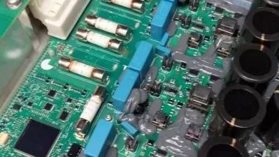
This hands-on course teaches power electronics firmware development using Microchip's PIC32CM MC microcontroller, covering GPIO, PWM, ADC, and timer modules with practical Curiosity Nano Kit projects.
What You'll Learn
- Program GPIO pins and configure interrupts for power electronics
- Generate precision PWM signals using TCC module with dead-time
- Implement analog signal processing with ADC for control systems
Who This Is For
- Undergraduate electrical engineering students
- Graduate students focusing on power electronics
- Firmware and test engineers in power systems
Key Benefits
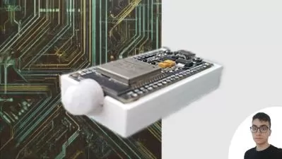
- Hands-on with Curiosity Nano Evaluation Kit
- MPLAB X IDE and XC32 compiler mastery
- Real-world power electronics firmware techniques
Curriculum Highlights
- System Setup & GPIO Programming
- Timer Modules & Clock Configuration
- TCC Module for PWM Generation
Focused display
- language english
- Training sessions 101
- duration 15:40:20
- Release Date 2025/06/02